


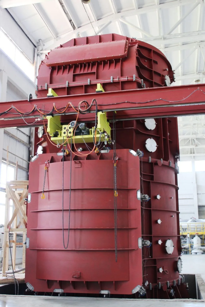
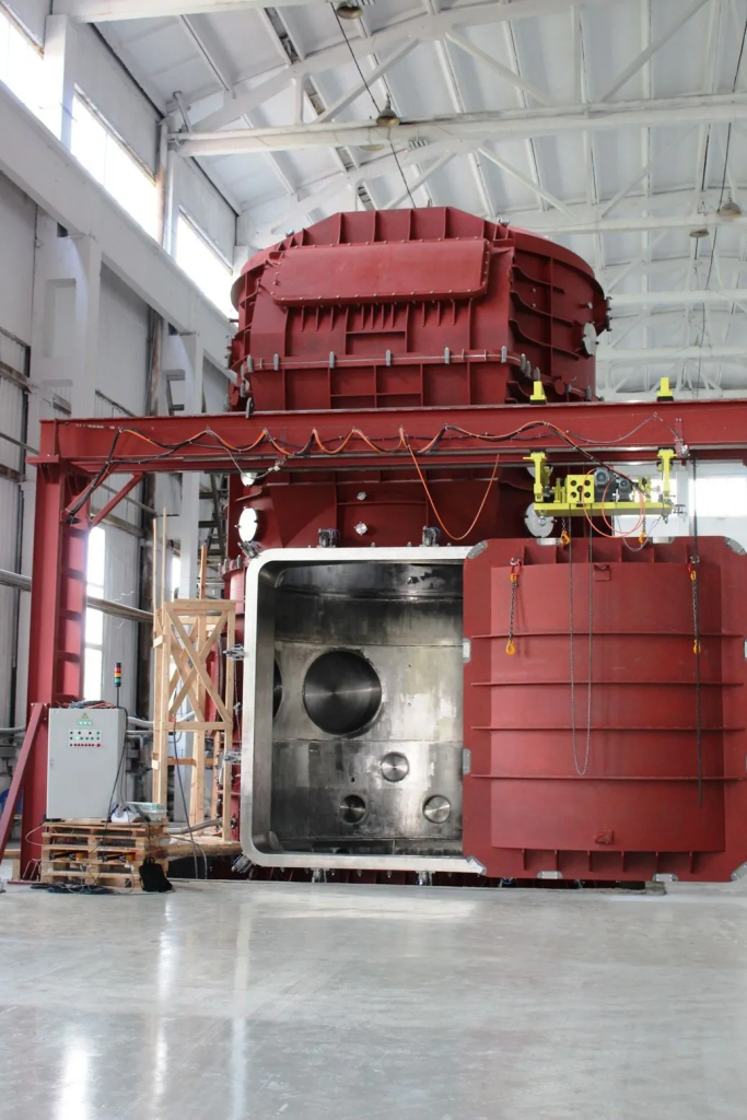
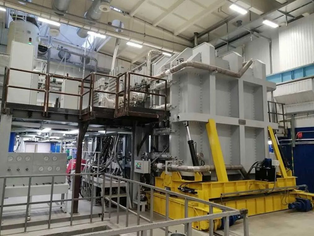
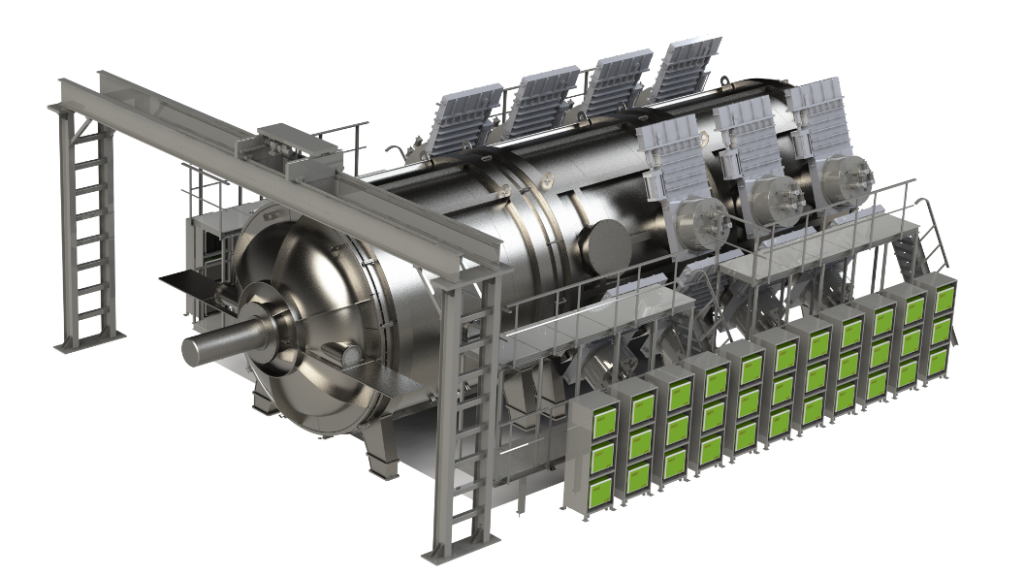
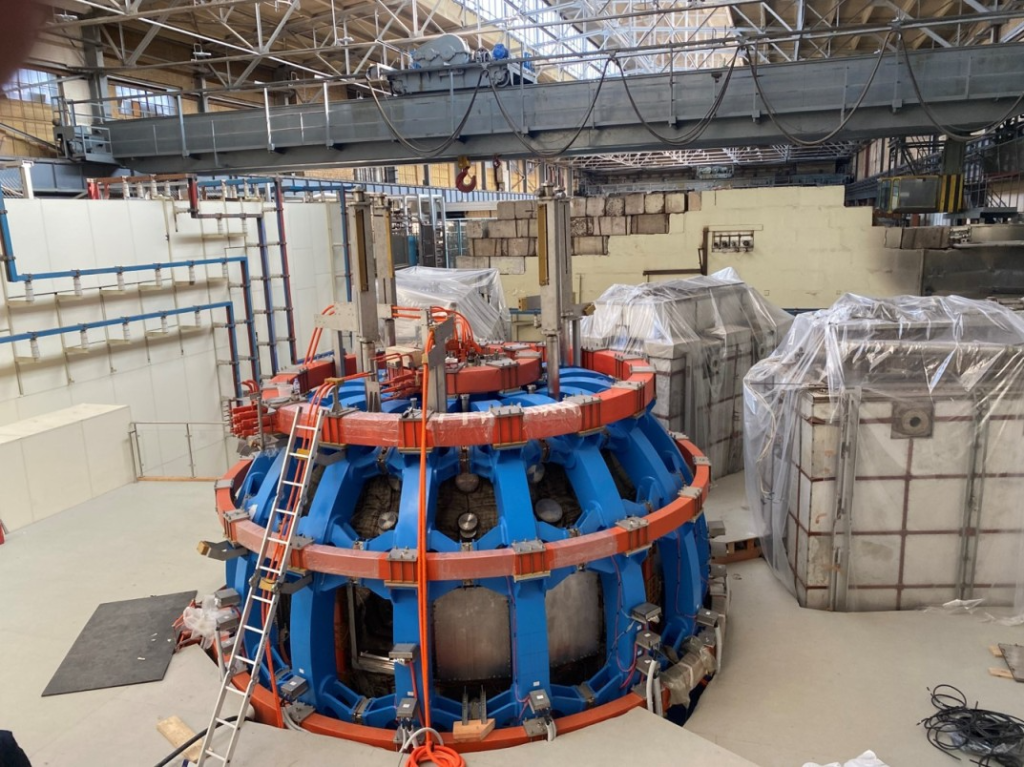
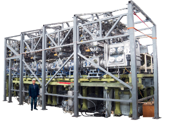
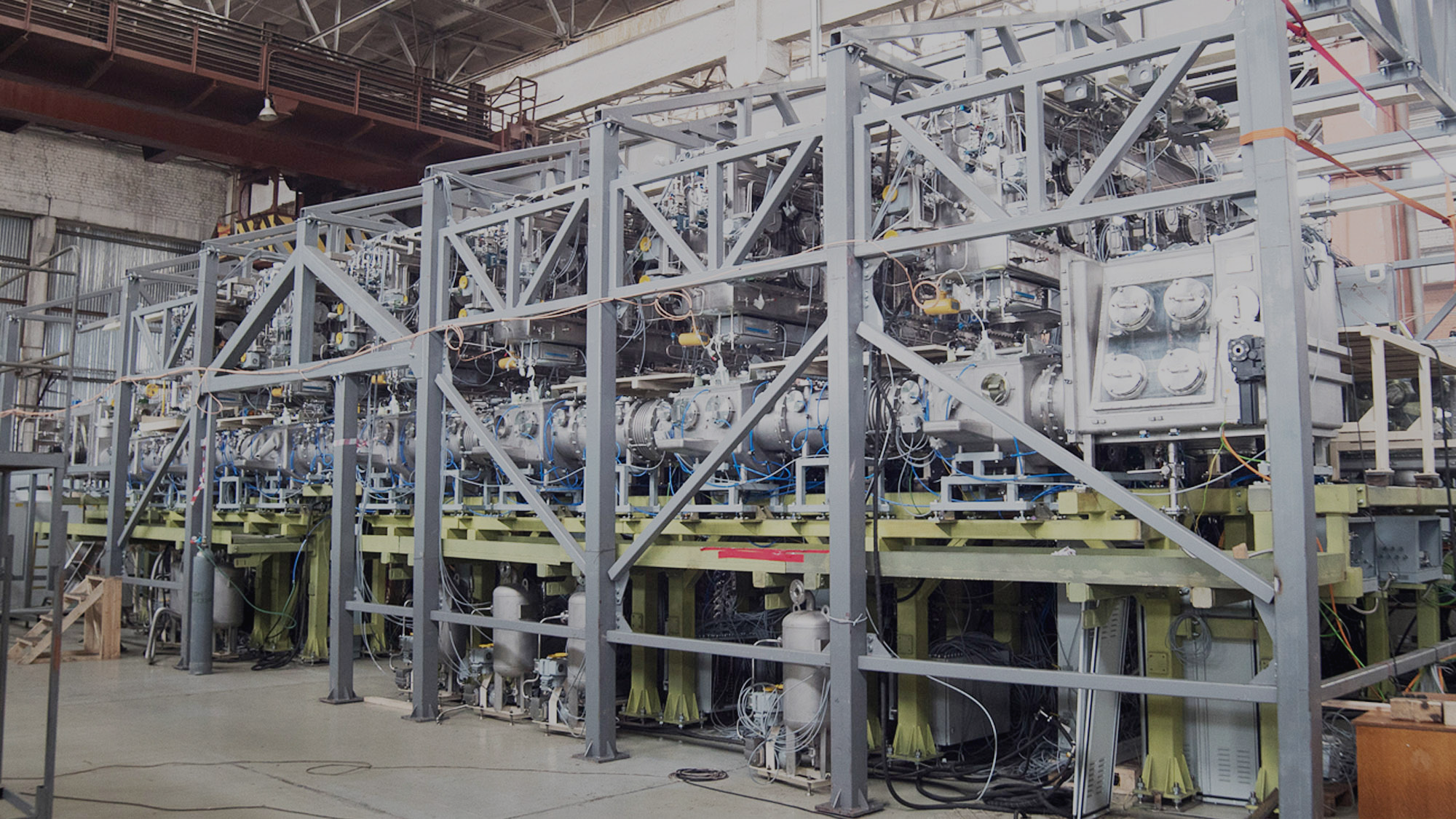
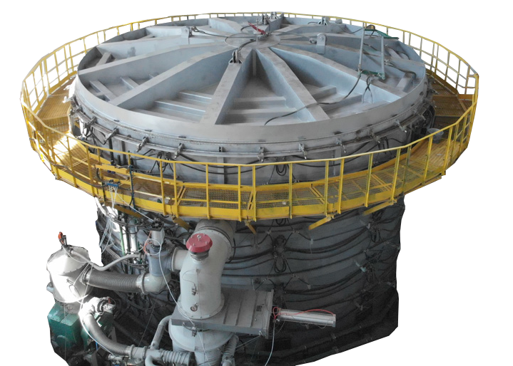
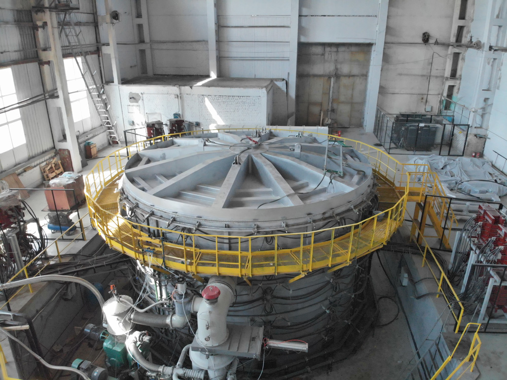
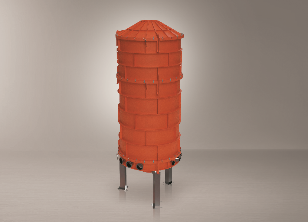
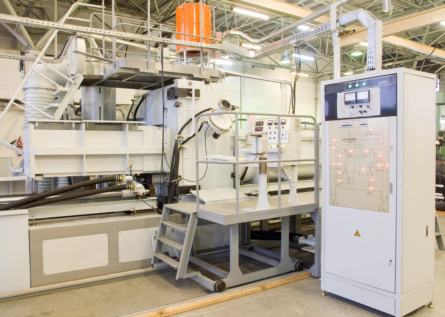
Thermal vacuum test facility (TVACF)
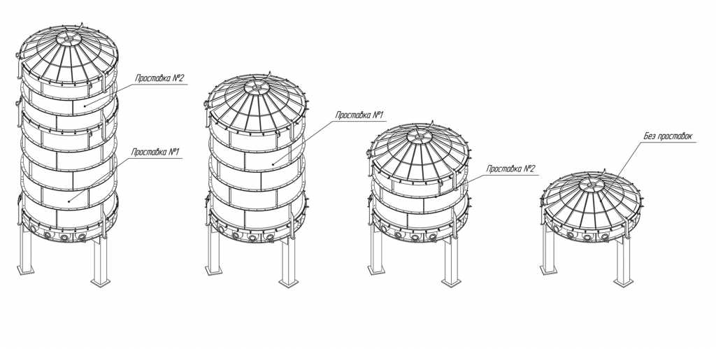
The effective diameter of the vacuum chamber is 5000 mm, the height is 10000 mm.
Moreover, the test facilities are designed to test electric and radio components, especially microchips and discrete modules in non-standard conditions. Commonly such facilities are used to test exposure to extreme temperatures and change of pressure in order to check the opportunity to use products in industry.
Depending on its purpose, the test facility can be a multifunctional system, chamber, bench or area. Test facilities are operated using a high-tech interface that enables to control the process and keepthe test results recorded by the computer at the same time.
TVACF cryogenic components:
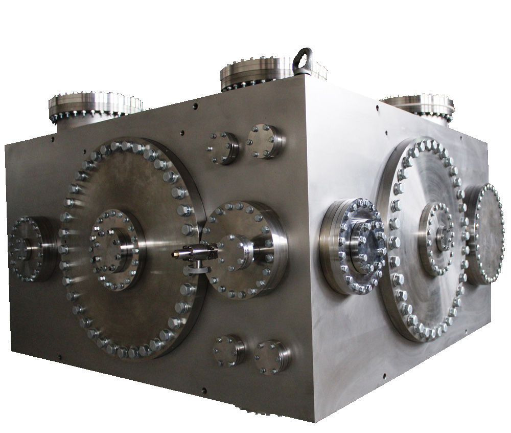
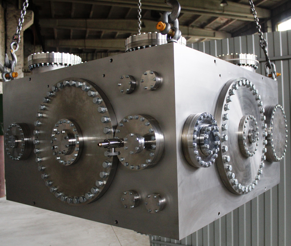
- Vacuum chamber
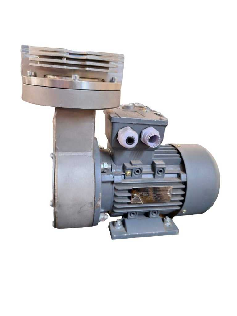
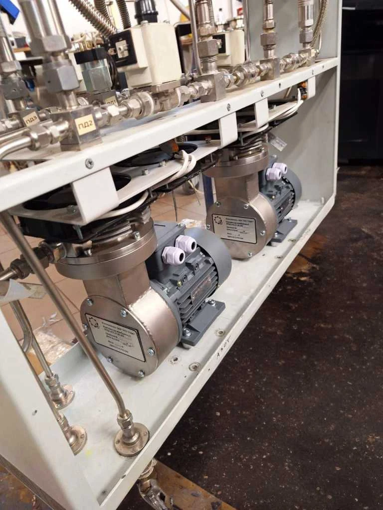
- Vacuum system
- Optical system for simulating radiation from point objects
- Optical system to simulate point-type object radiation
- Solar radiation simulation system
- Thermal flux simulation system
- High-precision hexapod to move and tilt objects

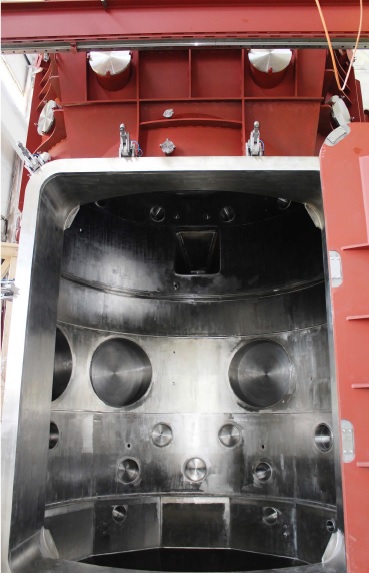

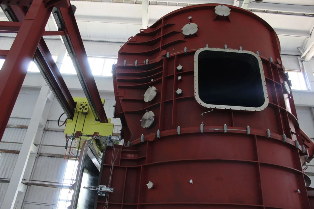
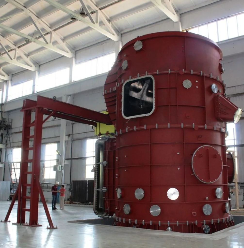

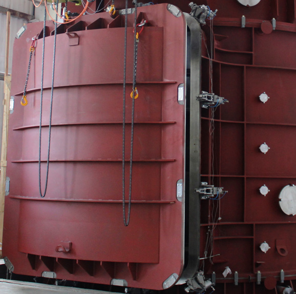
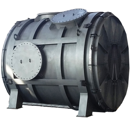
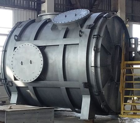
The thermal vacuum chamber consists of separate sections manufactured from corrosion resistive steel (AISI 3211). Its internal surfaces are polished, the roughness rate is Ra = 0.63 µm, the welded seams roughness is equal to Ra = 2.5 µm. Section are connected by flanges with seals – elastic viton cord with additionally vacuumed space between them. TVACF is mounted on vibration isolating supports to protect the TVACF-2 facility from any other outer vibrations.
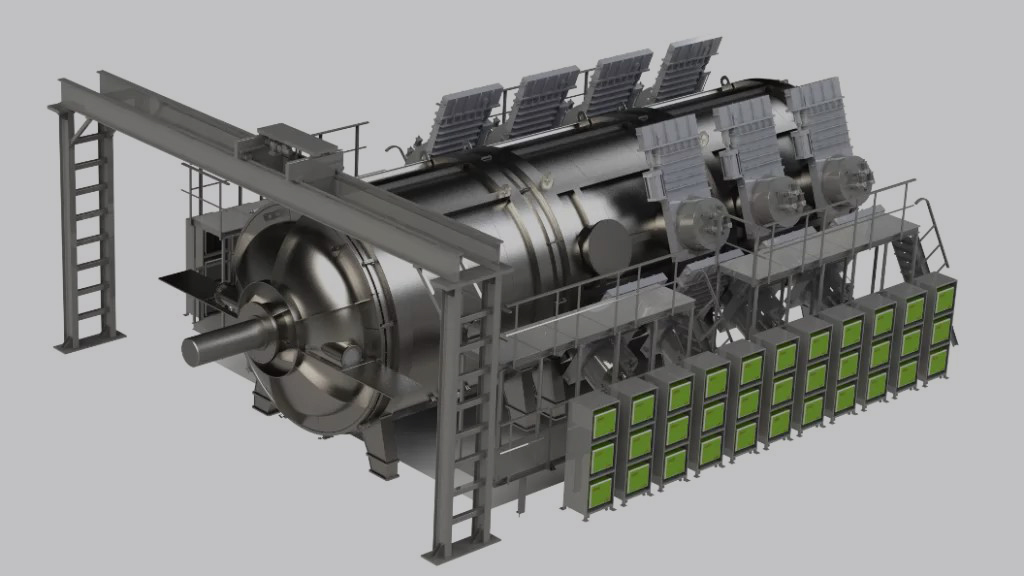
To load and unload the equipment under testinside the vacuum chamber we have designed a loading port with sliding leak-tight gates 2500 mm wide and 3500 mm height. The port is sealed by two elastic viton cord with additionally vacuumed space between them. The vacuum system uses serially produced vacuum pumps. TVACF-2 is a system of cryogenic screens with heat-exchange units cooled down my liquid nitrogen supplied by cryogenic system.
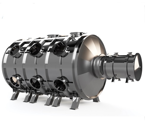
Heat simulation of vacuum environment is ensured by the system of cryogenic screens that pump through the liquid nitrogen with the help of gas-lift effect. The liquid nitrogen supply system includes cryogenic storage tanks, fueling nodes, cryogenic pipes with thermal blanket, as well as the liquid nitrogen separating device that ensures the coolant circulation. The optical system to simulate point-type object radiation is a two-channel cooling collimator with its components mounted on special movable supports to adjust and aim the system.
Solar radiation imitator is designed to create inside the vacuum chamber an almost parallel radiation beam with spectrum as close as possible to the extra atmospheric solar one with the cross-sectional irradiance from 1350 to 1900 W/m2.
Heat flux imitator (HFI) is to simulate heat fluxes in vacuum at cryogenic temperatures.
HFI includes:
- Infrared heater system of power supply units
- Set of cables
Other components of the TVACF-2 are managed by an automated control system. The architecture of the ACS, the associated software ensures development and upgrade of the control system by the user while operation by changing the hardware, devices, module and software configuration.
Our experts will gladly answer your questions.
Other products


Get your catalogue of Vacuum hardware and customized equipment
